






Incorrect neutral and earthing connections can cause problems that look like a faulty voltage stabilizer. The output voltage may fluctuate, an RCD may trip unexpectedly, or the equipment may behave differently when switched to bypass.
However, these symptoms do not always mean the automatic voltage regulator (AVR) is defective. The problem may be in the electrical installation.
Quick Answer: A voltage stabilizer’s metal enclosure must be connected to the installation’s protective earthing system. Neutral should be connected only where required by the stabilizer’s approved wiring diagram. Never use protective earth (PE) as a neutral conductor or add an extra neutral-to-earth connection inside the cabinet unless the approved system design specifically requires it.
The correct arrangement depends on the stabilizer model, power source, earthing system, connected loads, and protective devices.
This guide explains the difference between neutral and protective earth, six common wiring mistakes, and what to check before commissioning an industrial voltage stabilizer.
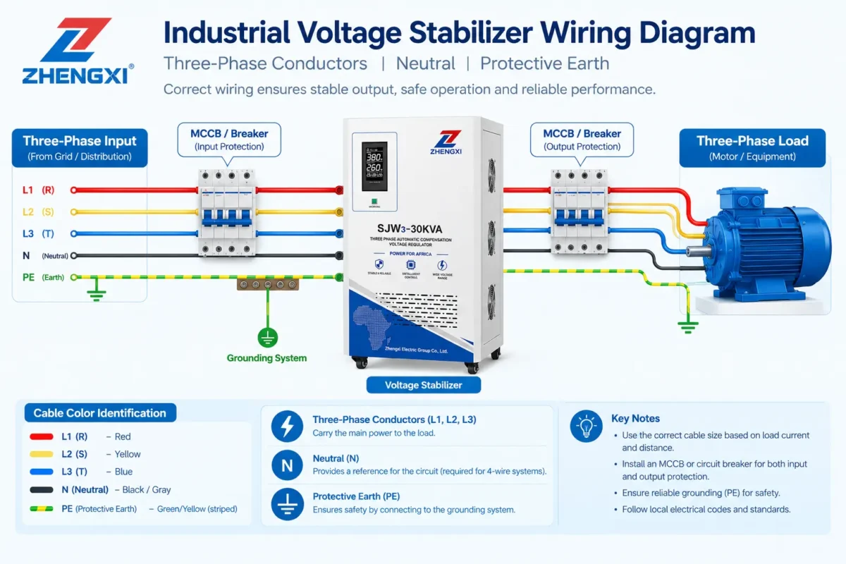
Understanding Neutral and Protective Earth
Before installing a voltage stabilizer, it is important to understand the different functions of phase, neutral, and protective earth conductors.
Although neutral and earth may be connected at a designated point in some electrical systems, they do not perform the same function.
| Conductor | Main Function | Important Requirement |
|---|---|---|
| L1, L2, L3 | Supply electrical power | Connect according to the rated phase configuration |
| N (Neutral) | Provides a return path for applicable loads and control circuits | Use only where required by the approved wiring design |
| PE (Protective Earth) | Bonds exposed conductive parts and supports fault protection | Must not carry normal load current |
| PEN | Combines neutral and protective functions in permitted TN-C sections | Must follow specific installation rules and must not be interrupted |
In a three-phase four-wire system, neutral may carry current when single-phase loads are connected or when the stabilizer’s control circuits require it.
Protective earth has a different purpose. It connects the stabilizer’s exposed metal enclosure to the installation’s protective system so that the designed fault-protection measures can operate.
A combined PEN conductor exists in certain electrical distribution arrangements, but it must not be treated as an ordinary interchangeable neutral or earth wire.
Key point: Neutral and protective earth are not interchangeable. A stabilizer cabinet should not be used to create a new neutral-to-earth bonding arrangement without an approved electrical design.
Does a Three-Phase Voltage Stabilizer Need Neutral?
Not every three-phase voltage stabilizer requires a neutral connection.
Some models are designed for a three-phase three-wire supply. Others use a three-phase four-wire configuration and may require neutral for voltage sensing, control power, or connected line-to-neutral loads.
The correct answer depends on the internal design of the stabilizer and its intended application.
For example, a three-phase stabilizer supplying only line-to-line loads may have different neutral requirements from a unit supplying multiple single-phase machines.
The stabilizer’s terminal markings and approved electrical schematic must determine the connection.
Before installation, check:
- Whether the equipment requires a three-wire or four-wire supply.
- Whether neutral is needed for the stabilizer’s internal controls or sensing.
- Whether the connected loads require a neutral conductor.
- Whether the neutral must remain continuous during bypass operation.
If the installation does not provide the neutral required by the selected stabilizer, the solution is not to connect its neutral terminal to PE.
Instead, the electrical designer should confirm whether a compliant neutral conductor can be provided or whether a suitable three-wire stabilizer model is available.
6 Common Voltage Stabilizer Wiring Mistakes
Many voltage stabilizer grounding and neutral problems result from incorrect conductor connections rather than a failure of the voltage regulation system itself.
The following six mistakes are particularly important in industrial installations.
1. Using Protective Earth as a Neutral
An installer may find three phase conductors and a protective earth conductor at the proposed stabilizer location, but no neutral.
If the selected stabilizer requires neutral, using PE as a substitute may appear to make its controls operate.
However, this can place normal return current on protective conductors and exposed metalwork. It may also interfere with residual-current protection and create dangerous potential differences.
Possible symptoms: Unexpected RCD trips, current flowing through PE during normal operation, or voltage differences between bonded metal parts.
What to check: Confirm the stabilizer’s actual neutral requirement and the approved supply arrangement. If neutral is required, it must be provided through a compliant electrical design.
Never use PE as a normal neutral return.
2. Connecting Neutral and Earth Inside the AVR
Another common mistake is adding a neutral-to-earth link inside the stabilizer cabinet.
This may be done with the intention of creating a stable voltage reference.
However, in systems where N and PE are required to remain separate downstream of a designated bonding point, an additional connection can create parallel return-current paths.
Current may then flow through protective conductors, cable armor, conduit, or other bonded metalwork.
It may also affect RCD operation and make fault protection less predictable.
Possible symptoms: RCD nuisance trips, unexpected PE current, or neutral current flowing through multiple paths.
What to check: Identify the actual source-earthing arrangement and the required neutral-to-earth bonding location.
The correct bonding point may differ between utility supply, isolation transformer, generator, and UPS arrangements.
Do not copy a generic online wiring diagram without verifying the site’s electrical system.
3. Loose, Broken, or Undersized Neutral
A loose or interrupted neutral can cause serious problems in a three-phase four-wire installation.
When single-phase loads are unevenly distributed across the phases, a poor neutral connection may cause line-to-neutral voltages to change as the load varies.
This can damage connected equipment even when line-to-line voltage readings appear relatively normal.
Neutral current can also be significant in systems supplying nonlinear loads. Certain harmonic currents, particularly triplen harmonics, may add in the neutral rather than cancel.
Possible symptoms: Fluctuating line-to-neutral voltage, changes in lighting brightness, intermittent control faults, or overheated neutral terminals.
What to check: Neutral continuity, terminal condition, conductor capacity, phase imbalance, and harmonic loading.
The neutral conductor must be sized and protected according to the actual electrical design, not simply assumed to carry little current.
A combined PEN conductor must not be interrupted by an ordinary switch or circuit breaker pole.
4. Poor Cabinet Grounding and Bonding
An industrial voltage stabilizer contains mains-voltage components inside a metal enclosure.
If a live conductor faults to the cabinet, the installation’s protective system must provide the intended fault-protection response.
Poor bonding can compromise this protection.
Common causes include loose earth terminals, corrosion, incorrect termination hardware, paint under bonding connections, or missing bonding straps where required.
A visible green-and-yellow conductor does not automatically prove that protective continuity is adequate.
Possible symptoms: Failed protective continuity tests, damaged bonding connections, or unexpected touch-voltage concerns.
What to check: The stabilizer’s PE terminal, enclosure bonding, protective conductor continuity, and the site’s fault-disconnection requirements.
An additional ground rod is not a universal substitute for the approved protective conductor arrangement.
5. Misreading Neutral-to-Earth Voltage
Measuring voltage between neutral and earth can be useful during troubleshooting, but a single reading does not establish whether the wiring is correct.
Some voltage between N and PE may occur under load because conductors have impedance.
A reading close to zero does not prove that the protective conductor is correctly connected or that the neutral-to-earth bond is in the proper location.
A high-impedance meter may also display an induced or “ghost” voltage on an open conductor.
Possible symptoms: Unusual N–PE readings, unstable voltage measurements, or apparently inconsistent readings at different locations.
What to check: The source arrangement, load current, instrument type, conductor continuity, and measurements at the source, stabilizer input, and stabilizer output.
Testing must be carried out by qualified personnel using appropriate procedures and instruments.
Do not diagnose a faulty stabilizer from one voltage reading alone.
6. Ignoring Neutral Wiring in Bypass Mode
Many industrial voltage stabilizers include a maintenance bypass or automatic bypass arrangement.
In normal regulation mode, power passes through the stabilizer’s designated circuit. In bypass mode, the load may be supplied through a different path.
If the neutral arrangement changes between these modes, an incorrectly designed changeover may interrupt neutral continuity or create unintended parallel connections.
Generator and UPS supplies can introduce additional earthing and neutral requirements.
Possible symptoms: Equipment behaving differently in bypass, unexpected protective-device trips, or changes in line-to-neutral voltage during source transfer.
What to check: The approved single-line diagram, bypass interlocks, neutral continuity, source-earthing arrangements, and protection requirements for every permitted operating mode.
If bypass supplies unregulated voltage, also confirm that the connected load can tolerate that voltage.
Voltage Stabilizer Grounding and Neutral Problems: Troubleshooting Table
If a stabilizer experiences unexpected trips or unstable voltage, the following table can help identify areas that require investigation.
| Problem | Possible Causes | What to Check |
|---|---|---|
| RCD trips when the AVR is connected | Unintended N–PE bond, leakage, incorrect bypass path | Trace neutral and PE connections through all operating modes |
| Line-to-neutral voltage changes with load | Loose neutral, broken neutral, load imbalance | Neutral integrity and phase currents |
| Cabinet has questionable touch voltage | Poor PE continuity, incorrect bonding, electrical fault | Isolate and verify the protective system |
| Output is normal without load but unstable under load | Cable voltage drop, loose connections, AVR overload | Voltage and current at the source, AVR, and load |
| Problem occurs only in bypass | Different neutral path, incorrect source arrangement, unregulated supply | Compare normal and bypass wiring diagrams |
These are possible causes, not definitive diagnoses.
If an unsafe condition is suspected, the equipment should be isolated and investigated by qualified electrical personnel before operation continues.
How Earthing Systems Affect AVR Wiring
Voltage stabilizer earthing requirements depend partly on the electrical distribution system.
IEC-based installations commonly use TN, TT, or IT earthing arrangements.
| Earthing System | General Arrangement | Main Consideration |
|---|---|---|
| TN-S | Neutral and PE remain separate in the distribution system | Maintain the designed separation and protective path |
| TN-C | A combined PEN conductor is used in permitted sections | Follow strict PEN requirements |
| TN-C-S | PEN is separated into N and PE at a designated point | Do not recombine them downstream |
| TT | Exposed conductive parts use a local earthing arrangement | Fault protection commonly relies on RCDs |
| IT | Source is isolated from earth or connected through impedance | Insulation monitoring and fault response require specific design |
These descriptions do not mean the installer should choose a different earthing system for the stabilizer.
The arrangement is determined by the electrical supply, transformer configuration, applicable standards, and site protection design.
If an isolation transformer is installed, its secondary winding may require a separately designed earthing and neutral arrangement.
The correct connection depends on the transformer configuration and the intended electrical system.
Important: A voltage stabilizer should not be assumed to provide galvanic isolation. If electrical isolation is required, confirm whether the selected equipment includes a suitable isolation transformer.
Pre-Installation and Commissioning Checklist
Before energizing an industrial voltage stabilizer, the installation should be reviewed against the approved electrical drawings and the manufacturer’s instructions.
| Check | What to Confirm |
|---|---|
| Power source | Utility, transformer, generator, and UPS arrangements |
| Earthing system | Actual TN, TT, or IT configuration |
| Terminal connections | Correct L1, L2, L3, N, and PE functions |
| Neutral conductor | Required continuity, capacity, and switching arrangement |
| Protective bonding | Cabinet and exposed conductive parts are properly bonded |
| Protective devices | Breaker, fuse, RCD, and fault-protection requirements |
| Bypass arrangement | Correct operation and protection in every permitted mode |
| Documentation | Test results, settings, drawings, and inspection records |
This checklist is intended for installation planning and commissioning review.
It does not replace the applicable electrical standard, site safety procedure, or manufacturer’s installation manual.
ZHENGXI Wiring Diagram and Technical Support
ZHENGXI manufactures industrial servo and static voltage stabilizers for different power supply and load requirements.
The neutral and protective earth connections of a voltage stabilizer depend on the specific model and electrical configuration.
For this reason, installation should follow the approved product wiring diagram rather than a generic stabilizer connection drawing.
For a three-phase industrial AVR, the technical review should confirm the input and output terminal arrangement, neutral requirements, protective earth connection, and any bypass configuration.
【img】
Alt: ZHENGXI three-phase industrial voltage stabilizer electrical cabinet showing power connection terminals and protective earth connection
Need the Correct Wiring Diagram for Your Voltage Stabilizer?
If you are preparing an installation or troubleshooting an existing stabilizer, please provide:
- Voltage stabilizer model and capacity
- Input and output voltage requirements
- Three-wire or four-wire supply configuration
- Site earthing system, if known
- Electrical single-line diagram
- Description of the problem and measured voltages, if applicable
- Clear photographs of the equipment nameplate and terminal labels
ZHENGXI can review the product-side requirements and provide relevant technical information for the selected model.
Email: service@zhengxi1983.com
The final earthing arrangement, protective devices, neutral switching, and installation design must be verified by the site’s qualified electrical engineer according to the applicable local standards.
FAQ
Not unless the approved electrical system design specifically requires the neutral-to-earth connection at that location. An additional N–PE connection in a system where the conductors must remain separate can create parallel return-current paths and affect protective-device operation.
No. Some three-phase stabilizers use a three-wire supply, while others require neutral for control circuits, voltage sensing, or connected loads. Follow the selected model’s approved wiring diagram.
Not necessarily. Effective protective earthing depends on the electrical system, protective conductor arrangement, and fault-protection design. A separate earth electrode does not automatically replace the required PE connection.
Possible causes include feeder voltage drop, phase imbalance, a loose neutral connection, or the stabilizer operating outside its rated capability. Measurements at the source, AVR input, and load are needed to identify the cause.
No. A broken or poor neutral is an electrical wiring fault that can create hazardous line-to-neutral voltages. The circuit should be isolated and repaired by qualified personnel.
Conclusion
Correct voltage stabilizer grounding and neutral wiring are essential for safe and reliable operation.
Neutral and protective earth serve different purposes. They must be connected according to the approved equipment diagram and the site’s electrical system.
Common mistakes such as using PE as neutral, adding an unintended N–PE bond, leaving loose neutral connections, or ignoring bypass wiring can create problems that voltage regulation alone cannot solve.
Before commissioning, confirm the conductor functions, protective bonding, neutral continuity, and protection arrangements for every operating mode.
If you need model-specific wiring information, contact ZHENGXI at service@zhengxi1983.com with the equipment model and electrical diagram. Have the final installation checked and approved by a qualified local electrical professional.
 EN
 FR
 ES
 PT