



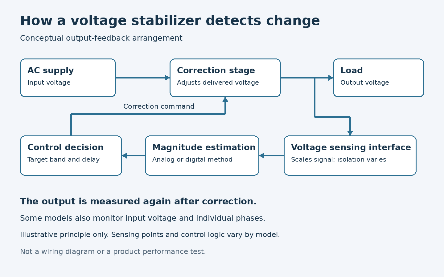
Un stabilisateur de tension automatique detects a voltage change through a sensing circuit connected to its input, output, or both. The circuit scales the AC signal to a safe level. A controller estimates voltage magnitude, compares it with a target range, and decides whether correction is needed. In three-phase units, the controller may also compare phases and watch for loss or imbalance. The sensing method and decision timing help determine which disturbances the stabilizer can actually address.
Detection is not the same as correction. A controller may notice a short dip yet be unable to correct it before it ends. Buyers should therefore ask how voltage is measured, how fast the unit responds, and what the connected machine can tolerate.
Why voltage sensing is more than reading a meter
AC voltage changes continuously through each cycle. An instantaneous sample is not the same as the supply voltage displayed on a multimeter. For most equipment ratings, the relevant magnitude is an RMS value over a defined time window. A control circuit must collect and process enough of the waveform to make a useful decision while avoiding false action on normal noise.
The sensing circuit commonly uses a transformer, divider, or other suitable interface to scale and isolate the voltage for electronics. The detailed design varies and must be checked in the model’s technical documentation. Calibration and component tolerances affect measurement accuracy. Where a display is fitted, its resolution is not necessarily the same as the controller’s accuracy or the output regulation accuracy.
A unit can monitor input voltage to know whether the source is within its permitted operating range. It can monitor output voltage to close the feedback loop and check what the load receives. Some designs monitor both. Ask which measured point controls regulation and which points trigger alarms or shutdown.
How is voltage magnitude calculated?
For a clean sinusoidal waveform, simple measurement methods can estimate RMS voltage from peaks or averages. Industrial waveforms are not always clean. VFDs, rectifiers, and other nonlinear loads can distort the waveform. A true RMS measurement method is more reliable for determining heating-related voltage magnitude when waveform shape changes, but even that does not by itself diagnose harmonics or transients.
The sampling interval matters. A short window can detect change promptly but may react to noise or a single unusual cycle. A longer window can produce a steadier decision but may miss or delay action on brief events. Product designers balance these goals. A published “response time” should state whether it includes measurement, controller decision, correction movement or switching, and settling at the output.
As an illustration, a nominal 400 V three-phase system measured at 380 V is 5% below nominal: (380 − 400) ÷ 400 × 100 = −5%. That tells the controller the direction of deviation. It does not mean the unit must act at exactly −5%; the action threshold and permitted band are model settings or design characteristics.
Why a controller uses a target band
If a stabilizer reacted to every tiny voltage change, it might continuously move a servo contact or switch electronic stages. A controller normally works with a permitted output band or other control rule. When output remains within that range, it can avoid unnecessary action. When voltage crosses a threshold for long enough, correction begins.
Hysteresis means the point at which correction starts can differ from the point at which it stops. This prevents repeated switching when voltage sits near a boundary. A time delay can serve a similar purpose for brief noise. Both features affect real-world behavior: a unit that avoids hunting may not react to a very brief dip. The buyer should compare those settings with the equipment’s actual sensitivity.
For example, if a controller senses a voltage change when a compressor starts, it may wait briefly before moving a servo mechanism. If the dip ends before that delay, no correction occurs. That may be appropriate if the connected machine tolerates the dip. If the machine resets during it, the solution may involve motor starting, feeder design, or a control UPS rather than a different nominal output-voltage setting.
What happens in a three-phase stabilizer?
Three-phase supplies require more than one voltage number. A controller may monitor all three line-to-line values, and on suitable four-wire systems may also examine phase-to-neutral values. It can check whether one phase is unusually low, high, or missing. Different stabilizers correct phases independently or through a shared arrangement. The difference matters when factory loads are unbalanced.
Consider a display showing an average of 400 V while actual phase-to-phase readings differ. The average could conceal one phase outside the connected equipment’s limit. Measure and log each phase at the affected machine. Ask the supplier whether the proposed unit senses and corrects each phase, how it handles an unbalanced input, and what its phase-loss protection does.
A failed or loose neutral in a three-phase four-wire network can produce dangerous phase-to-neutral differences. That is an electrical fault requiring qualified inspection. Do not treat an AVR’s alarm or correction function as a substitute for repairing the neutral.
Which events can the sensor see?
| Event | What sensing may show | Selection implication |
|---|---|---|
| Slow voltage drift | A changing RMS trend | Suitable candidate for regulation if within range |
| Brief motor-start dip | A short RMS event if sampling is fast enough | Compare duration with response and load ride-through |
| Very fast transient | May not appear in ordinary RMS log | Use transient-capable measurement and protection |
| Harmonic distortion | RMS may change; waveform is distorted | Measure harmonic spectrum separately |
| Phase imbalance | Different values by phase | Require phase-specific monitoring and engineering review |
| Complete interruption | Input voltage disappears | Regulation cannot supply power without storage |
“Detect” does not mean “solve.” A controller may alarm or disconnect rather than correct when voltage is outside its operating limits. The desired behavior should be stated in the procurement specification.
What affects detection accuracy and reliability?
Instrument and controller calibration. The sensing circuit must represent the real terminal voltage accurately. Ask about factory test methods and calibration requirements if tight output control matters.
Measurement point. Voltage at a stabilizer’s output terminals may differ from voltage at the end of a long downstream cable under load. If a machine remains low despite a normal stabilizer display, measure at the machine and inspect the feeder.
Waveform distortion. Nonlinear loads can affect simple sensing methods. Provide harmonic measurements or a description of major VFD and rectifier loads when asking for a solution.
Electrical noise and wiring. Control wiring layout and shielding can affect signal integrity. Follow the manufacturer’s installation instructions and use qualified personnel for commissioning.
Temperature and component drift. Industrial environments can be hot, dusty, or humid. Check the model’s specified ambient conditions, ventilation, enclosure, and maintenance requirements.
Protection logic. Some apparent “detection errors” are deliberate delays or threshold settings. Review event logs and the manual before adjusting controls.
How can a buyer test the sensing and response?
Ask for a test that records input and output waveforms or RMS trends during a defined input change. The record should show the starting voltage, ending voltage, load level, point at which the unit begins correcting, and time until output returns to its specified band. This is more informative than one response-time figure with no test definition.
For three-phase units, request phase-by-phase results under representative conditions. A test with a balanced resistive load may not show behavior under the site’s motor-start or unbalanced-load duty. The test does not need to reproduce every site event, but the differences should be stated so they are not mistaken for a guarantee.
At the factory, log input and output simultaneously during representative shifts. Use a separate, correctly rated meter or analyzer if independent verification is important. Compare readings at the stabilizer output with readings at the machine terminals. If they differ under load, the downstream distribution deserves attention.
When should a stabilizer act, alarm, or stop?
There is no universal answer. A modest, sustained input change within the rated range is a normal regulation case. An input outside the rated range may require an alarm or shutdown to protect the unit and load. Overload and phase loss may trigger other responses. Bypass may maintain power but expose the load to the unregulated source.
Define the operating philosophy for the process. A noncritical motor might be allowed to stop on a severe fault. A data or control system may need ride-through and a managed shutdown. Ask for a written description of the proposed model’s thresholds and actions, including whether settings can be changed and who is authorized to change them.
Information to send in an inquiry
Provide nominal and measured voltage on every relevant phase, frequency, minimum and maximum values, event durations, load kVA, peak current, starting method, equipment tolerance, and installation conditions. A voltage log and one-line diagram are more useful than the statement “voltage is unstable.” Include any observed waveform distortion or unusual phase imbalance.
ZHENGXI Electric can review automatic voltage stabilizer inquiries and OEM or ODM requirements. Ask for the proposed model’s sensing points, response-time definition, phase behavior, and test records. These details require model-specific confirmation.
FAQ
Does an AVR measure input voltage or output voltage?
Designs vary. Output feedback is useful for regulation, while input monitoring helps identify whether the source is within the permitted range. Ask for the model’s control diagram.
Why does the displayed voltage differ from my handheld meter?
Meters may use different measurement methods, averaging windows, calibration, and measurement points. Verify both instruments and measure the same terminals at the same time.
Can an AVR detect a millisecond transient?
An ordinary regulation sensor may not capture or characterize a very fast transient. Use a suitable power-quality instrument and specified transient protection when that is the concern.
Does faster detection always mean better protection?
No. The correction mechanism, overload capacity, and equipment ride-through also matter. An overly sensitive controller can react unnecessarily to harmless variation.
How do I check whether all phases are protected?
Request phase-by-phase sensing, correction, alarm, and protection details for the exact model. Verify them during commissioning under appropriate test conditions.
Résumé
Automatic stabilizers detect voltage changes by sensing an AC signal, calculating a meaningful magnitude, comparing it with control thresholds, and feeding the result to a correction mechanism. Measurement window, phase coverage, and protection logic determine how that process behaves in a factory. Send ZHENGXI Electric a phase-by-phase voltage log and load profile to obtain a model-specific technical review.
 FR
 EN
 ES
 PT